IFL and Amplifier Design Considerations
In or Out? That is the question satcom teleport operators and system engineers ask themselves these days. Should we continue with indoor, rack-mounted RF equipment, or move toward RF systems at the antenna? As in so many system design areas, the answer is … it depends.
Ongoing development of smaller and more powerful uplink satcom amplifiers, plus more powerful satellite transponders, have created the option of using less powerful outdoor equipment located directly at the antenna for many operators. Trade-offs based on frequency band, use of existing, new or modified equipment, and planned operations generate a range of answers. Here are a few key items and examples to consider when deciding “In or out?”
The largest factor affecting this decision is the link’s frequency band. While it’s possible to use indoor or outdoor equipment at any frequency, in some cases it doesn’t make much sense. With commercial C-band satcom frequencies, losses due to waveguide runs from a transmit amplifier located up to a hundred feet from the feed can be accommodated in typical link budgets. Figure 1 shows ideal loss in dB/meter of straight waveguides for satcom transmit bands from C to Ka. As operators transitioned large commercial satcom capacity to Ku-band, the drive to put transmit amplifiers close to the antenna feed began, since waveguide loss at Ku-band is 2.3 times the loss at C-band. Going to Ka-band increases waveguide loss of runs by a factor of 10 over C-band and a factor of 4.6 over Ku-band. Plus, cost per watt for Ka-band RF power is higher, so integrators came under great pressure to put Ka-band HPAs as close as possible to the feed. Incorporating L-band upconverters into outdoor equipment allows for low-cost, low-loss L-band interconnects over the longest distances in the system, which increases power efficiency.
Equipment and waveguide size is larger at lower frequency. For high power C-band systems, it can be impractical to locate all the RF on the antenna. However, waveguide losses for runs to the antenna are reasonable. For interim bands such as X (1.4x C-band loss), Ku (2.3x C-band loss), and the DBS band (3.1x C-band loss), the best solution might be either indoor rackmount or antenna mount outdoor – or either type in a small shelter at the antenna base. Since waveguide losses must be made up with higher amplifier power or antenna gain, outdoor configurations are generally considered for both DBS and Ku-band when feasible.
Another factor is the amount of RF power required at the antenna feed input for link closure. For older, less powerful satellite transponders, uplink equivalent isotropic radiated power (EIRP) requirements are much higher than those for newer, more capable satellites, especially above C-band where downlink power is limited for interference reasons. In addition, the antenna gain available from a given antenna size is significantly higher at higher frequency. A 3.8-meter antenna provides 12dB higher gain at Ka-band than C-band, since gain increases exponentially with frequency. So while it may be possible to close a link with a 3.8-meter antenna over a powerful Ka-band satellite using tens or a hundred watts of RF power, a kilowatt, or more, of RF power can be required to close a high data rate link through that same antenna over a limited capability C-band satellite. For links requiring very high transmit power, indoor rackmount amplifiers can make sense, including Klystron power amplifiers (KPAs) and Travelling Wave Tube Amplifiers (TWTAs) that provide kilowatts of RF power.
Cost of RF power varies by frequency band. Average cost per watt is similar at C- and Ku-bands, higher for DBS band and much higher for Ka-band. This is largely due to market forces (volume) and technology maturity, and changes over time. In determining where to locate your RF equipment, the cost of compensating for waveguide losses with even higher power amplifiers must be considered. Another key factor is the system redundancy architecture, which can impact the RF amplification system and usually results from a trade between system cost and availability. Can the system accept a brief link interruption while switching from primary to back-up? If so, a 1:1 switched system, where outputs of two amplifiers are switched between the feed and a load, will work. These can be configured for indoor rackmount either at the antenna base or in a hub mounted to the antenna.
In dual-polarization systems with a single antenna, two 1:1 amplifier systems can be replaced with a single 1:2 switched system to provide similar availability at lower cost with three amplifiers versus four. These fit on the antenna at the base, common for C-band, or in a hub on the rear of the reflector that moves with the antenna if it is repointed or tracking.
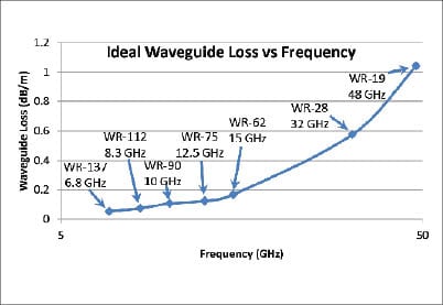
Figure 1 Ideal Waveguide Loss
If brief outages during switching are not acceptable, variable phase combined (VPC) approaches maintain phase during an event that shuts down an active amplifier. Although slightly larger and more complex, these avoid the long reacquisition sequence required when switched systems experience an amplifier shutdown. They can be located indoors with a rackmounted VPC hardware assembly or outdoors with a weatherized VPC box.
Softfail systems involving multiple operational amplifiers with both TWTA-based Continuous Power Systems (CPS) and solid-state modular rack-based hot-swappable systems provide continuous output at slightly reduced (by 1.2dB – 2.5dB) power when one of multiple output amplifiers fail. Some have output power auto-recovery if amplifiers were not in their full output power state, and remaining operating amplifiers are adjusted upward in gain and output power to reestablish the original output power. Some offer “hot-swap” capability to replace failed modules while operating.
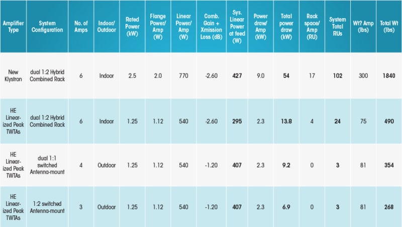
Figure 2. Ku-band Teleport Expansion, 50 ft Distance from Equipment Room to Antenna
Now that the key factors are understood, let’s take a look at a Ku-band example, where we consider a teleport operation looking to upgrade several Ku-band systems to increase capacity. They currently have indoor rack-mounted 2.4kW KPAs, each transmitting a single carrier and occupying one rack/amplifier. The upgrade plan is to keep a single carrier per amplifier, although future ability to add carriers may be valuable, and move to dual polarization on each existing antenna, along with higher data rates in current bandwidths using new bandwidth efficient modulation capability. For the higher data rates, additional RF power is needed. To add the second polarization, the number of active amplifiers must be doubled.
The current run from the equipment room housing the amplifiers to the existing antenna (50 foot waveguide run) results in a loss of 5 dB from the output of the rackmount KPA amplifier to the input of the antenna feed. The current 2.4kW KPAs produce 2kW at the flange and are backed off at least 4 to 5 dB in single-carrier operation, yielding operational amplifier output of 630 to 780W, which is reduced to approximately 200W (53 dBm) when it reaches the feed. The new system must provide 50 percent more operational power or about 300W (54.8 dBm) into the feed, for both polarization ports while maintaining redundancy switching capability.
Klystrons remain an option, since single-carrier operation doesn’t require more than the 75-85 MHz instantaneous bandwidth available from Klystrons and the redundancy doesn’t need a fast-tuner. However, 2kW Klystrons still each occupy half of a rack, weigh around 300 pounds, draw 9kW during operation and require significant air cooling. Figure 2 compares this with new high efficiency linearized peak TWTAs, power-combined as needed to achieve required output power for the indoor scenario.
Power combining is necessary for the indoor equipment case to meet the new higher transmit power, so a 1:2 hybrid combined system provides higher output power with a single redundant amplifier. For two polarizations, six amplifiers are needed to meet power and redundancy requirements. The indoor TWTA power combined option (Figure 2) is marginal on power to the feed so the loss budget would need optimization. For outdoor configurations, due to elimination of waveguide losses, power combining isn’t needed to meet required power. Four amplifiers provide dual 1:1 switched redundancy, or three amplifiers provide 1:2 switched redundancy; either one results in dramatic savings in acquisition costs and operational costs such as power consumption, rack space and air conditioning. They would even free up existing rack space so that the planned expansion can occur without adding to the equipment room. So for this system, the clear answer is: Out.
The answer for each system will be somewhat different depending on traffic served, frequency band, use of existing equipment, growth plans, redundancy requirements, and capital budget considerations, but there is a framework to systematically look at options available and assess their impact on performance, availability, capital cost, operations cost, and other teleport level benefits like reduced AC power infrastructure and air conditioning demands. But the trend is definitely moving toward “Out.”