Preventing Adjacent Satellite Interference
Satellite interference is a problem the entire industry must address. Over the years, much discussion has focused on how to identify the sources of costly RF interference so the problem can be eliminated as quickly as possible. One solution to help satellite operators and bandwidth managers mitigate accidental interference is to add a unique carrier identifier (CID) to the signal transmission. CID is a signal embedded into a transmission path that allows satellite operators and end users to work together to identify the source of the interference.
This was proven technically feasible back in 2006, but if manufacturers were expected to include CID in their monitor and measurement systems, it would be up to the operators and broadcasters to decipher the complexity of the real world when using CID on the receiving side. For example, what happens when a second carrier, 10dB below the first, is the interferer? In this article, we’ll address some of these hidden real-world issues and how they can be solved.
State of Carrier ID
Early testing by the Satellite Interference Reduction Group (sIRG) revealed that a modern digital communication system monitor (CSM) system was able to decode the digital video broadcasting (DVB) –S stream and read the network information table (NIT). Early CID systems were an aid to DVB signals, but what about single carrier per channel (SCPC) or fixed satellite services (FSS)? How can CID be used in those types of transmissions?
The main drawback of the NIT CID method is that it requires that the DVB-S stream be demodulated. This works well when the stream is well behaved on the satellite, but not so well at low signal-to-noise ratios; for example, when a signal is leaking into the cross pol and is becoming an accidental interferer.
A newer approach adds a metacarrier, or subcarrier, containing a unique identity transmitted under the spectral density of the main carrier. This method adds no extra bandwidth or power, and minimally affects the signal-to-noise ratio of the carrier as it places the CID signal within the host carrier bandwidth and below the noise floor of the signal.
From a transmission standpoint, this solution is very effective since it is a generic approach and appeals to SCPC and FSS operators. The major issue with subcarrier CID resides in the receiver side. The operator must have accurate measurement tools to demodulate the two signals and extract the CID from the interfering signal.
The hidden issues that lie within decoding the subcarrier CID signal starts with the way the signal is transmitted from the modem to the receiver.
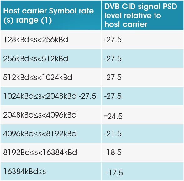
The subcarrier CID signal is transmitted as a BPSK carrier at one of two symbol rates, 224Ksymbols or 112KSymbols at +220Hz (no spectrum inversion) or -220Hz (spectrum inversion) from the host carrier center frequency at -27.5dB referenced to the host carrier spectral density. This level increases as the host carrier bandwidth increases as described in Table 1 below.
The CID carrier uses a baseband spreading technique and is chipped at the rate of 4096, giving processing gain within the receiver and allowing it to successfully decode the CID carrier.
The CID code is a 64-bit word encapsulated within the CID frame construction. At the beginning of each frame is a unique word that is set alternatingly to 0x147147 and 0x2b8eb8. A frame also includes an optional content ID, including Cyclic Redundancy Check (CRC) and Forward Error Correction (FEC) bits.
To identify and decode the CID once the interfering signal is detected, the center frequency of the host carrier will need to be measured to determine the center frequency of the CID. Accurate measurement of this center frequency is critical since the CID center frequency is either +220Hz, plus measurement uncertainty of the host due to the transmission coming from different modem manufacturers.
Given that the CID spectral density is low compared to that of the host, the CID will normally be at, or below, the transponder noise floor. This is especially true when the host is an interfering carrier. It is to be expected that the host be tagged as an interferer when it is 10dB below the main carrier, leaving the CID 37.5dB below the maximum spectral density of the main carrier.
The CID uses a 4096 chip rate to spread the data set, giving a potential processing gain of 36dB on the de-spread side. In the scenario described above, this would be insufficient to demodulate the CID, so another technique is needed to improve the CID signal-to-noise. This is the hidden issue that lies within the receiver side of subcarrier CID. In order to decode the CID on the carrier, carrier separation (main-to-host) must be employed so CID detection is available.
The Hidden Challenge of CID Decoding
Fundamentally, it would seem that decoding the CID would be relatively simple: lock onto the CID carrier, look for the unique word header, regenerate the carrier clock, de-spread the carrier data to create a positive carrier-to-noise ratio, and then decode the CID frame.
However, any receiver needs a starting point that is an accurate measurement of center frequency of the carrier to be captured. Accurate measurement of the host carrier center frequency and data rates would allow the receiving system to be programmed +220 hertz at the correct capture bandwidth. In this case, accurate means to the order of +10Hz or for Ku-band 1 in 108. Center frequency of this accuracy can only be measured by a dedicated receiver or a modern digital CSM. In the case of the host being an interferer, its center frequency and data rate can only be measured by a CSM system capable of carrier-under-carrier measurements.
Suppose a broadcaster with a MCPC DVB-S2 signal occupying 36MHz of bandwidth is being interfered with by a narrow carrier. Once the host carrier parameters are determined, the CID receiver needs to determine if the CID carrier is +220Hz or -220Hz from the host center frequency. This is achieved by creating two receivers with built-in software and firmware to search for either of the unique words.
The CID is -37.5dB below the large DVB carrier. There is insufficient processing gain from the chip rate alone to receive a positive SNR for the CID in this case. However, the same frame is repeated four times, yielding another 12dB of possible gain at the expense of time. The knowledge that all four are identical can add more processing gain, but the time to capture the data takes as a maximum of 32 seconds. This length of time would preclude standard CSM carrier-under-carrier techniques from being a viable method to detect and demodulate the CID. Specific CID receivers must be built within firmware and software to be generic for all carrier types, data rates and frequency bands.
Accuracy is the Heart of Subcarrier CID
![monics-a_carrier_under_carrier[1]](https://www.satellitetoday.com/wp-content/uploads/2014/04/monics-a_carrier_under_carrier1.jpeg) CID is an effective tool to combat RF interference. The cases in which CID can be effective are greatly increased by using subcarrier CID over NIT CID as it supports many more signal types. However, the hidden challenge in using subcarrier CID is that decoding them relies entirely on the accuracy and ability to measure the center frequency of the signal.
CID is an effective tool to combat RF interference. The cases in which CID can be effective are greatly increased by using subcarrier CID over NIT CID as it supports many more signal types. However, the hidden challenge in using subcarrier CID is that decoding them relies entirely on the accuracy and ability to measure the center frequency of the signal.
As CID technology improves, satellite operators and end users will be able to identify and quickly mitigate accidental RF interference.